 English
 简体中文
简体中文
Views: 0 Author: Site Editor Publish Time: 2026-07-10 Origin: Site


Industrial and commercial water systems face a demanding challenge. They must achieve massive pressure increases. Facilities cannot rely on oversized motors or catastrophic energy consumption to reach these goals. Single-stage pumps operating near their limits simply cannot keep up. When pushed too hard, standard units suffer from premature wear. They also experience severe hydraulic inefficiency.
The multistage centrifugal pump solves this engineering hurdle. It divides the pressure-building workload across multiple impellers. This approach creates a modular, highly efficient solution. It excels in demanding high-head applications.
This guide provides engineers and facility managers with a solid framework. We will help you specify these complex systems accurately. You will learn how to balance performance data against installation realities. We will also explore material selection, configuration types, and strict sizing parameters.
Hydraulic Efficiency: Staged impeller designs generate high pressure linearly, requiring significantly less motor horsepower than single-stage equivalents for identical high-head tasks.
Material Reliability: Stainless steel (304/316L) configurations prevent the iron oxide contamination common in cast iron pumps, making them mandatory for sanitary, RO (Reverse Osmosis), and aggressive fluid systems.
Configuration Flexibility: Choosing between vertical and horizontal orientations depends strictly on facility footprint, piping infrastructure, and maintenance clearance.
Vendor Due Diligence: Sourcing an OEM multistage pump requires verifying the manufacturer’s hydraulic testing capabilities, ISO compliance, and aftermarket parts availability.
To understand the value of staged pumping, we must look inside the casing. Fluid enters the first impeller and gains kinetic energy. It then passes through a diffuser. The diffuser converts this velocity into static pressure. It also guides the fluid into the eye of the next impeller. This cycle repeats across every stage. Flow remains constant throughout the entire journey. However, head (pressure) increases cumulatively at each step.
Engineers often try pushing a single large impeller to high speeds. This approach creates problems. It causes excessive radial loads on the pump shaft. It also severely increases cavitation risks. Bearings wear out quickly under these extreme conditions. A staged design avoids these mechanical stresses entirely. It builds pressure incrementally. This keeps shaft deflection low. It also allows the motor to operate within a highly efficient performance window.
Despite these benefits, you must face implementation realities. These units excel at generating massive pressure. They do not handle solids well. The internal clearances between impellers and diffusers are extremely tight. Solid particulate matter will easily jam or erode these precision components. Upstream filtration is a strict requirement. We recommend installing Y-strainers or bag filters before the pump inlet. This simple step prevents catastrophic internal damage.
Choosing your pump orientation is a critical design step. You must base this decision on physical facility constraints. Piping layouts dictate your options. Maintenance team capabilities also play a large role.
Vertical configurations are incredibly popular. They offer a minimal floor space footprint. You can integrate them directly into straight-line piping runs easily. This inline design makes them excellent for commercial building applications. You will frequently see them in HVAC and municipal pressure boosting setups.
However, they have drawbacks. You need significant vertical clearance above the unit. Technicians must lift the heavy motor straight up during routine maintenance. If your mechanical room has low ceilings, this orientation will cause headaches.
Horizontal orientations provide a distinct set of advantages. They maintain a lower physical profile. Technicians can access internal components easily. They usually do not have to disturb the primary motor or surrounding piping. These units handle much higher flow rates. They dominate heavy industrial applications.
The trade-offs are space and alignment. They demand significant floor space. You must install them on a rigid, perfectly leveled baseplate. Poor baseplate alignment leads directly to vibration. Vibration quickly destroys mechanical seals and bearings.
Use the following table to guide your selection process. It compares critical facility requirements against pump orientations.
Decision Factor | Vertical Inline Pump | Horizontal Pump |
|---|---|---|
Floor Space Available | Ideal for tight spaces and crowded mechanical rooms. | Requires a large, dedicated footprint. |
Vertical Clearance | Requires high clearance for motor hoists. | Fits well in low-ceiling environments. |
Piping Layout | Best for straight, continuous pipe runs. | Best for complex or offset industrial piping. |
Flow Capacity | Moderate to high. | Extremely high. |
Vibration Control | Self-contained, minimal alignment needed. | Demands strict baseplate leveling and alignment. |
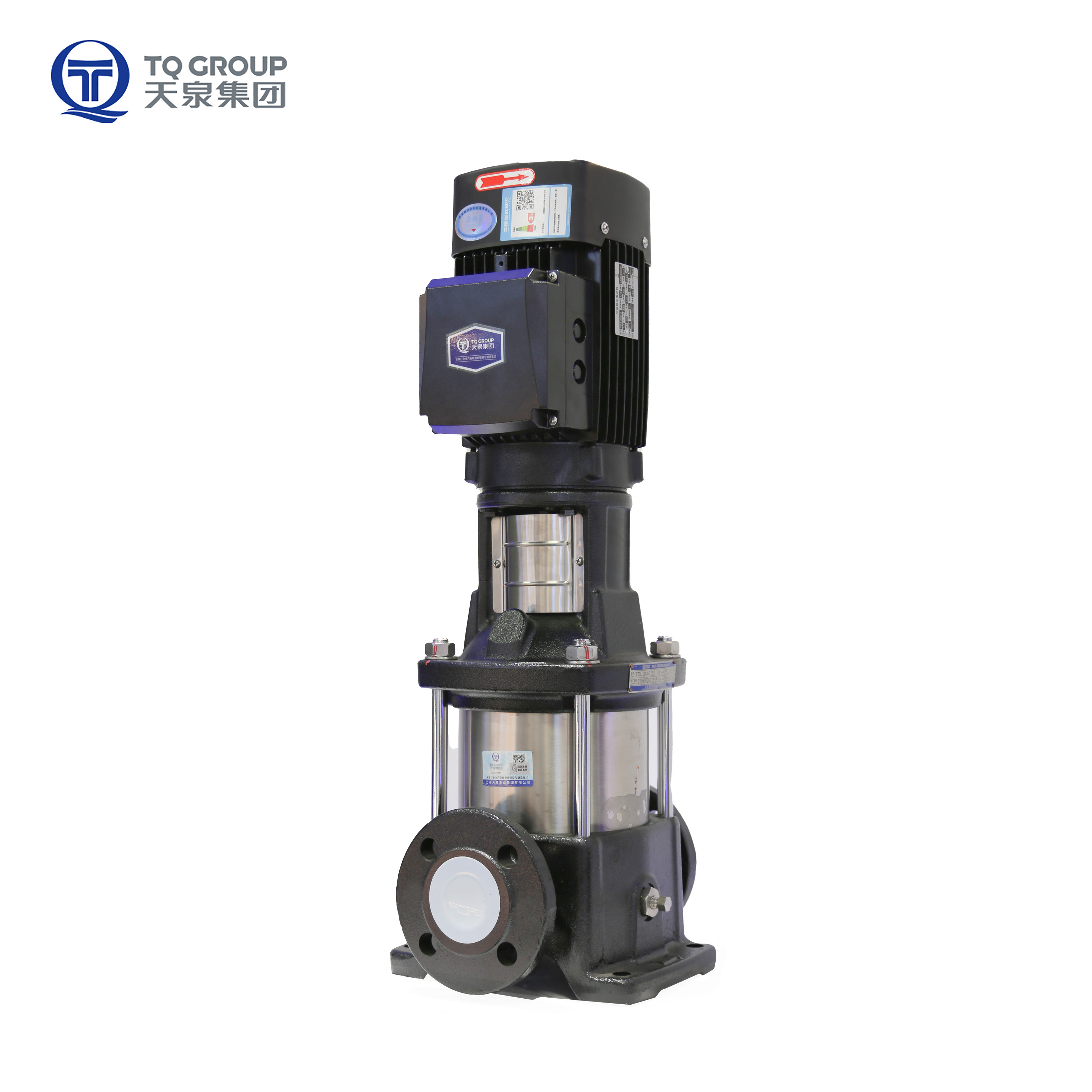
Proper sizing prevents premature system failure. You cannot simply guess the required metrics. You must carefully analyze the fluid dynamics of your specific network. Reading the manufacturer performance curve is your first step.
System designers plot Flow Rate (Q) against Total Dynamic Head (H). Every pump operates best at its Best Efficiency Point (BEP). You should select a high pressure booster pump that operates near this BEP. Multi-staging is the industry standard method for achieving extreme extremes. For example, specifying a 300m head pump is routine for deep-mine dewatering or commercial boiler feeds. A single impeller could never hit 300 meters of head efficiently.
Calculating NPSH requires deep engineering expertise. It prevents a destructive phenomenon known as cavitation. Cavitation occurs when fluid drops below its vapor pressure inside the pump. This creates tiny bubbles. These bubbles collapse violently against the metal impellers. They pit the steel and destroy the pump.
You must strictly follow this mathematical rule: NPSHa (Available) must always exceed NPSHr (Required). We recommend keeping a safety margin of at least 1 meter.
Be aware of specific risk warnings. Booster units placed in series are highly susceptible to vapor lock. Systems drawing from low-pressure atmospheric tanks face similar risks. If you do not calculate NPSH rigorously, your system will fail quickly.
Modern pumping requires smart motor control. Follow these steps when specifying your drive system:
Analyze Load Variations: Determine if your flow demands fluctuate throughout the day.
Specify a VFD: Pair your unit with a Variable Frequency Drive. VFDs adjust the motor speed to match exact system demands.
Size the Motor: Ensure the motor is non-overloading across the entire performance curve.
Program Ramps: Set soft-start and soft-stop parameters on the VFD. This eliminates water hammer risks.
Using VFDs significantly reduces energy consumption. It also drastically extends the mechanical lifespan of the entire unit.
Fluid chemistry dictates your material choices. You cannot use cast iron for everything. Cast iron rusts easily. It contaminates process fluids with iron oxides. A stainless steel multistage pump is mandatory for aggressive or sensitive liquids.
Stainless steel comes in different metallurgical grades. You must match the grade to the application.
304 Stainless Steel: This is the industry standard for light duty. It is highly suitable for municipal water boosting. You will also see it in light commercial HVAC systems. It handles non-corrosive industrial liquids perfectly well.
316L Stainless Steel: This grade contains molybdenum. It offers superior corrosion resistance. It is strictly required for brackish water applications. You must use 316L for pharmaceutical processes, sanitary food transfers, and mild acid handling. It also performs better in high-temperature environments.
We must be transparent about material limits. Even 316L stainless steel is not invincible. It is not immune to high concentrations of chlorides. Chlorides cause pitting and stress corrosion cracking. You must specify exact temperature ranges and chloride PPM limits. If chloride levels exceed standard thresholds, you must upgrade. Duplex stainless steel or pure Titanium components might become necessary.
The mechanical seal is the most vulnerable component. It prevents fluid from leaking out along the spinning shaft. You must choose seal faces and elastomers based on fluid chemistry.
For clean water, Carbon versus Ceramic faces work fine. However, high-pressure industrial tasks require tougher materials. Silicon Carbide (SiC) or Tungsten Carbide (TC) faces withstand extreme friction. For elastomers, choose EPDM for hot water applications. If you are pumping oils or mild chemicals, Viton (FKM) is the superior choice. Matching the seal to the fluid prevents unexpected downtime.
Selecting the right manufacturing partner is crucial. Sourcing an OEM multistage pump requires rigorous due diligence. You are not just buying metal. You are investing in long-term operational reliability.
Every facility has unique regional compliance laws. A credible OEM must offer engineering flexibility. Ask them specific customization questions. Can they modify flange standards to match DIN or ANSI pipework? Can they install specialized mechanical seals at the factory? Do they offer diverse motor voltage options to meet your local electrical grid requirements? Flexibility indicates engineering depth.
Never accept a unit without proof of performance. Quality manufacturers test every unit before shipment. You must demand certified hydraulic performance curves. These documents prove the unit hits your required flow and head. You should also request hydrostatic pressure test reports. Hydrostatic testing ensures the casing will not rupture under extreme operational pressures.
Many buyers ignore the aftermarket reality. This is a common mistake. You must evaluate the availability of standard replacement kits. Check if they readily stock seals, bearings, and O-rings.
We offer a highly practical piece of advice. Avoid vendors who lock buyers into proprietary consumable parts. Some manufacturers design unique mechanical seals. They do this to force you to buy expensive parts directly from them. If they experience a supply chain disruption, your facility goes offline. Standardized mechanical seals lower long-term maintenance friction. They ensure you can always find replacement parts from local industrial suppliers.
Specifying the right equipment requires balancing multiple technical variables. You must carefully align your required head and flow with the correct physical footprint. Choose a vertical or horizontal orientation based on your exact mechanical room layout. Always select the proper material grade (304 or 316L) to combat fluid corrosion.
Your next steps are clear and actionable. First, finalize your fluid parameters. Document the exact temperature, specific gravity, flow rate, and head requirements. Second, calculate your NPSH available. Finally, approach your shortlisted engineering partners. Request a detailed pump curve and a comprehensive material specification sheet. This evidence-based approach guarantees a reliable, highly efficient installation.
A: No. Dry running will immediately destroy the mechanical seal and internal bearings. These internal components rely on the pumped fluid for cooling and lubrication. Dry-run protection sensors or flow switches are absolutely mandatory in your system design to prevent instant failure.
A: Standard commercial configurations typically handle fluid up to 120°C (248°F). However, specialized high-temperature mechanical seals and modified internal clearances can push this limit higher. In industrial boiler feed applications, upgraded units can safely handle up to 180°C (356°F).
A: Under clean fluid conditions and optimal operation on the pump curve, impellers can easily last 10 or more years. Premature wear is almost always a symptom of a larger system problem. Cavitation, abrasive particulates, or running the unit dead-headed will destroy impellers rapidly.


