 English
 简体中文
简体中文
Views: 0 Author: Site Editor Publish Time: 2026-07-13 Origin: Site


Industrial fluid management demands massive capital investment. When critical pumping systems fail unexpectedly, operations face paralyzing downtime costs. Single-suction pumps frequently struggle under high flow rates. They battle relentless axial thrust and severe cavitation risks. Over time, these hydraulic forces cause premature bearing failure. Plant managers are then forced into complex, labor-intensive maintenance cycles. You need a more robust architecture for continuous duty.
Enter the split case centrifugal pump. It stands as the definitive solution for high-volume applications. Reliability and in-line serviceability are non-negotiable in these environments. In this guide, we will explore the engineering mechanics behind these heavy-duty units. You will learn how to evaluate specific design criteria for your facility. We will also cover sourcing strategies and installation realities to maximize operational lifespan.
Design advantage: The double suction architecture intrinsically balances axial thrust, significantly extending bearing and mechanical seal lifespan.
Maintenance efficiency: Axially split casings allow rotor removal without disconnecting suction or discharge piping, drastically reducing Mean Time To Repair (MTTR).
Application scope: Ideal as an industrial flow pump for HVAC cooling towers, municipal water distribution, fire protection, and heavy manufacturing.
Sourcing strategy: Selecting between a standard catalog pump and a custom OEM split case pump depends on specific hydraulic duty points, material compatibility, and footprint constraints.
Understanding the internal mechanics of a double suction centrifugal pump reveals why it dominates heavy industry. The primary advantage lies in its unique hydraulic balancing. In standard end-suction designs, fluid enters one side of the impeller. This single-entry point creates immense unilateral pressure. It pushes the shaft axially toward the suction side. Over time, this constant thrust degrades mechanical seals and destroys thrust bearings.
Double suction models solve this problem fundamentally. Fluid enters the pump casing and splits into two identical streams. The streams enter both sides of the impeller symmetrically. Opposing hydraulic forces effectively cancel each other out. This intrinsic balance eliminates severe axial thrust. It allows the equipment to run smoothly for decades under continuous heavy loads.
Another critical engineering benefit is the reduction in Net Positive Suction Head required (NPSHr). Industrial environments frequently face challenging suction conditions. High temperatures, low tank levels, and long pipe runs lower the available suction head. By splitting the flow path, the impeller eye handles half the velocity of a comparable single-suction unit. Lower inlet velocities drastically reduce NPSHr. This drop mitigates cavitation risks. It protects the impeller vanes from pitting and eventual structural failure.
Finally, we must look at structural integrity. A typical end-suction unit uses an overhung design. The impeller hangs off the end of a shaft, supported only at one side. Heavy fluid loads cause shaft deflection. This bending ruins seals and causes rapid wear. Conversely, a split casing design features a rigid between-bearings architecture. Bearings support the shaft on both ends of the impeller. This support system minimizes shaft deflection. It ensures the mechanical seals run true, vastly extending their operational life.
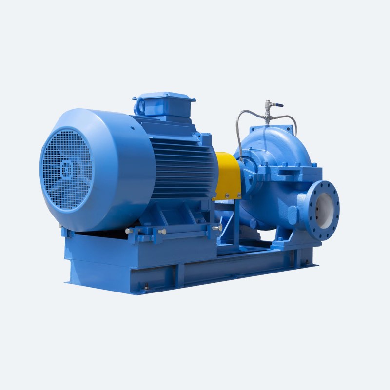
Specifying the correct equipment requires rigorous evaluation. You cannot simply pull a model off a shelf. You must match the hydraulic capabilities strictly to your facility needs. An oversized industrial flow pump wastes energy and creates mechanical instability.
Hydraulic coverage dictates your starting point. You must map your specific duty points, tracking both required flow and total dynamic head. Plant engineers often select an impeller trimmed precisely to the Best Efficiency Point (BEP). Operating at or near the BEP minimizes energy consumption. It also reduces hydraulic turbulence inside the casing. Pumps running off their BEP experience severe radial loads. These loads shorten bearing lifespans drastically.
Material selection proves equally critical for aggressive environments. Standard cast iron and bronze configurations work perfectly for clean, ambient-temperature municipal water. However, heavy manufacturing often involves corrosive or abrasive media. Corrosive fluids demand specialized metallurgy. Engineers frequently specify Duplex stainless steel for its exceptional resistance to pitting and chloride stress cracking. Evaluating the fluid composition ensures you avoid catastrophic material degradation.
Facilities must also comply with rigorous specification standards. Your regulatory environment dictates these frameworks. Oil and gas refineries generally mandate API 610 compliance. This standard ensures maximum safety and reliability for petroleum processing. Fire protection systems require NFPA 20 certification. General industrial applications might only need standard ISO compliance. You must match the build standard to your industry requirements.
Heavy-duty applications frequently demand a SOW split case pump variant. These specific single-stage, double-suction volute casing designs excel in demanding settings. You will typically find them in raw water intake facilities, power plant cooling loops, and heavy mining operations. Their robust volute casings handle suspended solids better than standard commercial models.
Metallurgy Comparison Chart
Material Configuration | Primary Application | Corrosion Resistance | Durability Profile |
|---|---|---|---|
Cast Iron / Bronze Trim | HVAC, Municipal Water, Fire Systems | Low to Moderate | Excellent for clean fluids; susceptible to abrasive wear. |
Standard Stainless Steel (316) | Chemical Processing, Light Industrial | High | Resists mild acids; vulnerable to high chlorides. |
Duplex Stainless Steel | Desalination, Mining, Aggressive Fluids | Exceptional | Superior resistance to pitting, abrasion, and stress cracking. |
Theoretical benefits mean little without practical implementation. The true value of horizontally split equipment emerges during routine maintenance. Standard end-suction models require workers to disconnect massive suction and discharge piping to access the impeller. This process takes days and requires heavy rigging equipment.
Conversely, servicing a split casing design offers a profound maintenance advantage. Technicians simply unbolt and lift the upper casing half. The piping remains entirely undisturbed. This access allows rapid inspection or replacement of the entire rotating assembly. To fully realize this reduced Mean Time To Repair (MTTR), maintenance teams usually follow strict protocols.
Isolate the equipment by closing the suction and discharge valves completely.
Drain the volute casing using the bottom drain plugs.
Remove the coupling guard and disconnect the motor coupling.
Unbolt the upper casing half and carefully lift it using overhead hoists.
Inspect or extract the rotor assembly, wear rings, and bearings as a single unit.
Despite these maintenance advantages, you must account for space requirements. Horizontally mounted units require a substantial floor footprint. They take up significantly more room than vertical inline alternatives. Facility managers must balance superior maintenance access against premium floor space. If a mechanical room lacks square footage, you might consider vertical split case options. These models stand upright. They act as a spatial compromise. They retain the hydraulic benefits of the double suction impeller while reducing the required floor area.
Installation criticality cannot be overstated. A pump is only as reliable as its foundation. Implementation requires massive, rigid baseplates. Installers must properly grout these baseplates into the concrete floor. This grouting absorbs vibrations and anchors the equipment permanently. Following grouting, technicians must perform a precision laser alignment. Traditional dial indicators often fall short for heavy industrial units. Laser alignment ensures the motor shaft and pump shaft match perfectly. Misalignment by even a few thousandths of an inch will destroy couplings and bearings prematurely.
Even the most robust equipment can fail if poorly applied. Engineering teams frequently fall into the trap of over-sizing. They add excessive safety margins to flow and head specifications during the design phase. A consultant might add ten percent for pipe wear, and another ten percent for future expansion. Consequently, the purchased unit is far too large for the actual system demand.
Over-sizing creates severe operational risks. The equipment is forced to operate far to the left of its Best Efficiency Point. Operating off BEP causes internal fluid recirculation. This recirculation generates intense heat and severe vibration. The shaft deflects under unnatural radial loads, destroying mechanical seals rapidly. You must size the equipment for actual operational realities, not hypothetical worst-case scenarios.
Seal and bearing failures also arise from improper initial piping installation. The between-bearings structural design is inherently strong, but it cannot support the weight of your building's piping. Pipe strain occurs when installers force misaligned pipe flanges to mate with the pump flanges. This forces the casing out of alignment. It pinches the bearings and warps the shaft slightly. To avoid negating the structural benefits of the pump, adhere to these best practices:
Support all suction and discharge piping independently from the casing.
Ensure pipe flanges align perfectly with the equipment before installing bolts.
Never use the flange bolts to pull piping into place.
Install expansion joints if thermal expansion will push against the casing.
Procurement teams must choose between standard catalog models and custom-engineered solutions. Knowing when to rely on off-the-shelf units saves valuable time. Standard models are best suited for predictable environments. These include typical municipal water distribution and standard HVAC chilled water systems. They also serve well in urgent replacement scenarios. If your duty requirements closely match a catalog specification, a standard model provides rapid delivery and reliable performance.
However, complex industrial processes often demand a custom OEM split case pump. Standard units fail under extreme edge cases. You must specify an OEM unit when dealing with non-standard electrical voltages or extreme fluid temperatures. Bespoke skid integration also requires OEM engineering. If you pump proprietary fluid compositions with unusual specific gravities, off-the-shelf hydraulics will not perform correctly.
An OEM relationship also grants access to crucial testing capabilities. Heavy industry cannot afford unverified performance. Manufacturers can provide witnessed factory performance tests. They run the unit on a test stand to verify flow, head, and efficiency before shipping. Hydrostatic testing guarantees the casing will safely contain maximum system pressures. These verifications ensure your equipment operates safely from day one.
When selecting your manufacturing partner, you need a strict vendor evaluation checklist. Do not decide purely on initial lead times. Look deeply into their post-sale support infrastructure.
Vendor Evaluation Checklist
Evaluation Category | Key Considerations | Warning Signs |
|---|---|---|
Spare Parts Availability | Verify localized stock for wear rings, impellers, and mechanical seals. | Components ship only from overseas; lead times exceed 8 weeks. |
Engineering Support | Direct access to application engineers; transparent warranty terms. | Support handled exclusively by third-party distributors. |
Documentation Quality | Comprehensive provision of specific pump curves, dimensional drawings, and manuals. | Generic, unbranded manuals; inability to provide certified performance curves. |
The final verdict is clear. Implementing this pump architecture represents a strategic infrastructure investment. These robust machines are designed for decades of high-efficiency, high-volume fluid transport. Their between-bearings design and balanced suction paths protect against wear. Their accessible casings ensure maintenance teams can return systems to service rapidly.
Your next step requires careful analytical action. Encourage your engineering team to verify Net Positive Suction Head available (NPSHa) meticulously. Calculate precise duty points rather than relying on bloated safety margins. Consult directly with application engineers early in your design phase. By matching rigorous hydraulic analysis with the correct manufacturing partner, your fluid handling systems will achieve maximum operational reliability.
A: The main differences lie in fluid entry, bearing placement, and maintenance access. Split case models feature double suction entry, balancing hydraulic thrust. They support the shaft between two bearings, minimizing deflection. Maintenance involves removing the top casing half without disturbing piping. End-suction units use single suction, overhung bearings, and require a back-pull-out method for maintenance.
A: Yes. Vertical configurations exist specifically to minimize floor space. They retain all the hydraulic benefits of a balanced double suction impeller. However, vertical mounting usually requires technicians to remove the heavy electric motor to perform comprehensive maintenance on the rotating assembly.
A: Severe vibration typically stems from installation or operational errors. Misalignment during laser installation and excessive pipe strain on the flanges are common mechanical causes. Hydraulically, operating too far left or right of the Best Efficiency Point (BEP) causes radial vibration. Inadequate NPSHa also triggers cavitation, which vibrates the entire casing.


