 English
 简体中文
简体中文
Views: 0 Author: Site Editor Publish Time: 2026-09-09 Origin: Site


Factory cooling water circulation systems act as the beating heart of modern industrial operations. They prevent critical thermal bottlenecks and ensure continuous production uptime. Without reliable fluid transport, excessive heat quickly stalls even the most advanced manufacturing processes. Engineers often face complex challenges when choosing equipment for these demanding thermal loops.
Improper specifications lead to massive energy waste, premature mechanical seal failure, and system-wide inefficiencies. Over time, these engineering errors create cascading disruptions across the entire plant floor. You cannot afford unexpected facility downtime due to poorly matched fluid handling equipment.
This guide provides an objective, highly practical framework to evaluate your equipment options. We will explore how to properly size, specify, and align the ideal solution for your unique thermal load. You will learn actionable strategies to prevent cavitation, optimize piping design, and maximize long-term mechanical reliability.
End suction pumps offer the optimal balance of flow capacity, maintenance accessibility (back pull-out design), and upfront cost for open and closed-loop cooling towers.
Accurate calculation of Net Positive Suction Head Available (NPSHa) is non-negotiable to prevent cavitation in cooling applications.
Total Cost of Ownership (TCO) relies heavily on matching pump efficiency curves with system demands and utilizing VFD-compatible motors.
Correct suction piping design (e.g., straight runs, eccentric reducers) is just as critical as the pump specification itself.
We often see various equipment types in industrial facilities. However, the end suction pump remains the absolute industry standard. Let us briefly contrast this design against common inline and multistage alternatives. Inline models save floor space. Yet, they become notoriously difficult to service when motor sizes exceed 20 horsepower. Multistage units excel at generating high pressure. However, cooling towers rarely require massive head pressure. They need high fluid volume instead.
This makes the single-stage, horizontal layout incredibly advantageous. Standard industrial plant rooms offer ample floor space. A horizontal configuration fits these standard layouts perfectly. It keeps the motor and casing close to the ground. This low center of gravity minimizes dangerous vibrations. It also simplifies structural support requirements across the facility floor.
Maintenance realities drive the preference for these units. A defining feature is the "back pull-out" design. Maintenance teams appreciate this engineering choice immensely. Mechanics can easily remove the motor, coupling, and impeller assembly. They do this without disturbing the main suction or discharge piping. You never have to drain the entire system just to replace a mechanical seal. This drastically reduces expensive facility downtime.
Hydraulically, these units hit the exact sweet spot for thermal management. Factory chillers and open cooling towers typically demand high flow rates at moderate head pressures. Single-stage impellers deliver these specific hydraulic conditions efficiently. They operate smoothly across a wide performance curve. This inherent flexibility handles varying seasonal temperatures effortlessly.
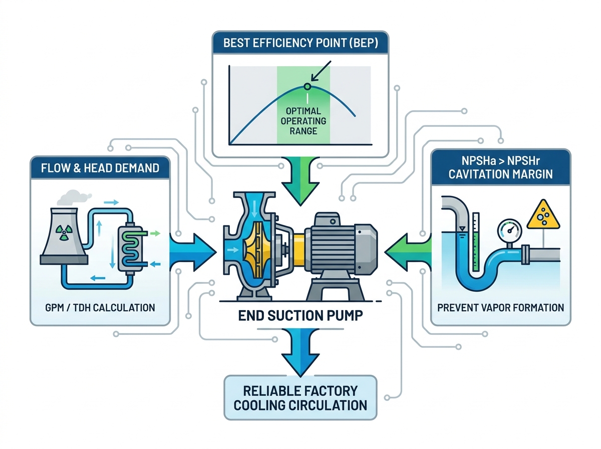
Proper factory cooling water circulation pump selection requires strict adherence to hydraulic fundamentals. You must establish baseline flow (GPM or LPM) and Total Dynamic Head (TDH) accurately. The factory’s peak thermal load dictates the flow rate. The cooling tower manufacturer usually specifies the exact fluid volume required per ton of cooling.
Calculate TDH by mapping the entire piping circuit. Include static lift from the basin to the tower spray nozzles. Add friction losses from all pipes, valves, elbows, and heat exchangers. You must evaluate the system curve carefully.
Beware of a common engineering trap known as "safety factor stacking." An engineer might add a 10% safety margin to the flow. The piping designer then adds 10% to the friction loss. Finally, the contractor selects the next larger motor size. This severe oversizing pushes the equipment far off its Best Efficiency Point (BEP). Operating off-peak causes excessive vibration, increased shaft deflection, and premature bearing failure. You must specify the exact system demands without artificial inflation.
Cavitation prevention demands rigorous attention. You must understand the relationship between Net Positive Suction Head Required (NPSHr) and Available (NPSHa). NPSHr represents the pressure required to keep fluid from boiling inside the casing. The manufacturer provides this curve. NPSHa represents the actual absolute pressure available at the suction nozzle.
You must ensure NPSHa exceeds NPSHr by at least a 3 to 5 foot margin. Cooling applications present a unique challenge. Warm return water possesses a higher vapor pressure. As temperature rises, fluid inches closer to its boiling point. This reduces your available NPSHa significantly. If available pressure drops below required pressure, vapor bubbles form. These bubbles collapse violently against the impeller. Cavitation destroys metal surfaces in weeks.
Material compatibility rounds out the core evaluation. Factory environments frequently utilize aggressive water treatment chemicals. These biocides and scale inhibitors attack inferior metals. Evaluate the fluid chemistry carefully. Standard applications often use cast iron casings paired alongside bronze impellers. Bronze resists general corrosion well. However, if your water contains high chlorides or suspended solids, upgrade your materials. Stainless steel impellers offer superior resistance to both chemical attack and physical erosion.
Long-term performance depends on motor integration and robust mechanical choices. Energy efficiency plays a massive role in operational success. Industrial thermal loops run continuously. Therefore, you should always integrate Premium Efficiency (IE3) or Super Premium Efficiency (IE4) motors. These modern motors reduce electrical consumption drastically. They also run significantly cooler. Cooler operation extends winding insulation life and improves overall reliability.
You must also evaluate Variable Frequency Drives (VFDs). Many systems experience fluctuating thermal loads. Production demands shift throughout the day. Seasonal weather changes affect cooling requirements. A VFD allows the motor to slow down during partial load conditions. According to affinity laws, reducing speed by 20% cuts energy usage by nearly 50%. You must ensure the chosen motor is inverter-duty rated. Standard motors overheat when run at low speeds.
Mechanical seal selection heavily influences maintenance intervals. Open cooling towers scrub dust, dirt, and organic matter from the atmosphere. This debris enters the water stream. Standard carbon-on-ceramic mechanical seals struggle in these dirty environments. The suspended solids scratch the softer carbon faces quickly. This leads to premature fluid leaks and unexpected downtime.
For open systems, specify hard-face mechanical seals. Silicon carbide on silicon carbide is highly recommended. Silicon carbide withstands abrasive particles exceptionally well. It costs slightly more upfront but prevents catastrophic leaks later.
Lifecycle maintenance planning ensures continuous plant uptime. Engineers build credible reliability models using L10 bearing life standards. The L10 standard calculates the hours 90% of bearings will survive under specific loads. Industrial applications demand a minimum L10 life of 50,000 hours. Operating strictly near the BEP minimizes radial thrust. Low radial thrust preserves these bearings. A properly specified and aligned unit routinely operates for 15 to 20 years.
The finest equipment fails quickly if you install it poorly. Correct suction piping design is absolutely critical. Turbulent fluid entering the impeller causes noise, vibration, and performance loss. You must provide a smooth, uniform flow profile to the suction nozzle.
Follow strict suction piping rules. Specify a minimum of 5 to 10 pipe diameters of straight, unobstructed run directly before the inlet. Never install a 90-degree elbow directly on the suction flange. If space limitations force an elbow, utilize a specialized suction diffuser to straighten the flow.
Reducer orientation is another frequent failure point. Suction pipes are typically one size larger than the pump inlet. This reduces friction loss. You must install a reducer to connect them. On horizontal lines, always use an eccentric reducer. Install it with the flat side facing up.
Concentric reducers create a high spot in the pipe. Air bubbles accumulate in this high spot. Eventually, a massive air pocket releases into the impeller. This air-binds the equipment and breaks the fluid column. The flat-top eccentric design eliminates this trap entirely.
Design Element | Common Mistake | Engineering Best Practice |
|---|---|---|
Suction Pipe Sizing | Matching pipe size exactly to the pump flange size. | Sizing pipe one to two sizes larger than the flange. |
Reducer Selection | Using concentric reducers on horizontal runs. | Using eccentric reducers installed flat-side up. |
Inlet Straight Run | Installing elbows directly onto the suction flange. | Maintaining 5 to 10 pipe diameters of straight pipe. |
Discharge Piping | Supporting heavy valves directly on the pump casing. | Supporting all piping independently from the baseplate. |
Vortexing prevention requires careful basin design. Open cooling towers pull water from a shallow sump. If the suction pipe lacks proper submergence, a whirlpool forms. This vortex pulls massive amounts of surface air down into the pipe. Follow Hydraulic Institute standards to calculate the required submergence depth based on fluid velocity. Add baffle plates to the basin if depth is severely limited.
Baseplate installation and alignment finalize the implementation. Never bolt the baseplate directly to uneven concrete. You must level the baseplate and fill it entirely with non-shrink epoxy grout. Grouting dampens operational vibrations permanently. Finally, mechanics must perform a precision laser alignment. Do this only after connecting all pipes. Pipe strain often distorts the casing and throws the motor out of alignment.
When navigating specific procurement choices, the TQWT horizontal end suction cooling tower pump stands out as an exceptional baseline. This specific model maps perfectly to demanding factory environments. It translates rigid engineering specifications into reliable daily outcomes.
Let us break down its core design features. Hydraulic stability represents its primary advantage. The volute casing and impeller geometry minimize internal turbulence. This ensures smooth operation even when facility heat loads fluctuate wildly. Its operational footprint remains compact. Yet, it strictly maintains the crucial back pull-out serviceability standard. Mechanics appreciate this robust layout.
Material configurations suit continuous industrial duty. You can specify highly durable casing materials to withstand aggressive biocides. The shaft and bearing housings utilize heavy-duty designs. They easily absorb the radial loads generated during continuous 24/7 operation.
Consider this shortlisting logic when evaluating options. Here are application scenarios where this model serves as the optimal choice:
Your facility utilizes an open cooling tower subject to airborne debris.
Your thermal loop experiences varying loads requiring VFD integration.
Maintenance teams require rapid seal replacement without dismantling heavy piping.
The mechanical room has standard horizontal layout space available.
Water chemistry demands robust, corrosion-resistant impeller materials.
This unit checks every critical box for industrial thermal management. It balances performance and longevity beautifully.
Making the right procurement decision safeguards your entire facility. The correct horizontal centrifugal unit aligns strict hydraulic requirements with long-term mechanical reliability. It balances flow capacity, material durability, and maintenance accessibility perfectly. Always remember proper piping design remains just as vital as the equipment itself. Eliminate air pockets and ensure smooth suction flow.
Take immediate action to secure your system. Gather your exact baseline requirements today. You must document your required GPM, the calculated TDH, and your maximum fluid temperature. Double-check your available suction head to guarantee safe operation.
Finally, reach out to a certified engineering specialist. They will provide a custom curve analysis tailored to your exact facility layout. Professional guidance ensures your industrial cooling loop operates efficiently for decades.
A: Ensure adequate NPSHa exceeds NPSHr by at least three to five feet. You achieve this by minimizing suction lift and reducing suction pipe friction. Also, monitor fluid temperature closely to manage vapor pressure. Warm water boils easier, which drastically lowers your available pressure margin.
A: Yes, absolutely. You must ensure the paired motor is specifically inverter-duty rated. VFDs are highly recommended for factory cooling loops. They allow the system to adapt dynamically to variable heat loads, saving massive amounts of electrical energy.
A: Industrial units typically operate reliably for 15 to 20 years or more. Achieving this lifespan requires precise laser alignment, operation near the Best Efficiency Point, and routine maintenance of mechanical seals and bearings.
A: It prevents the formation of trapped air pockets at the top of the horizontal pipe. Concentric reducers create high spots where air gathers. This air eventually gets drawn into the impeller, causing severe vibration, loss of prime, and reduced hydraulic performance.


